Joel H. Gutierrez III

Rocket Scientist. Future Entrepreneur. Texan.

Filtering by Tag: Georgia Tech

DADsat (Senior Capstone Design Project)

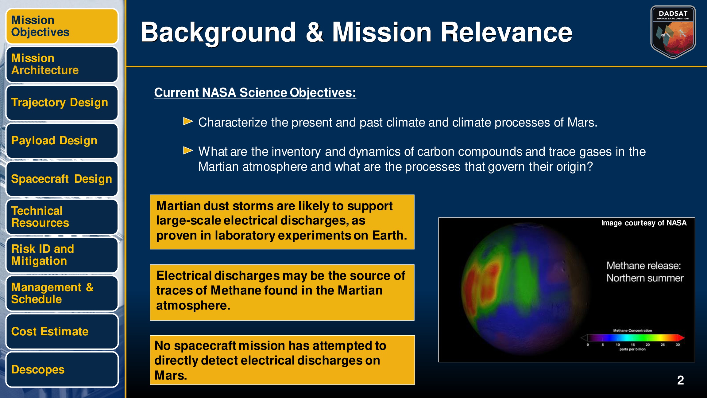
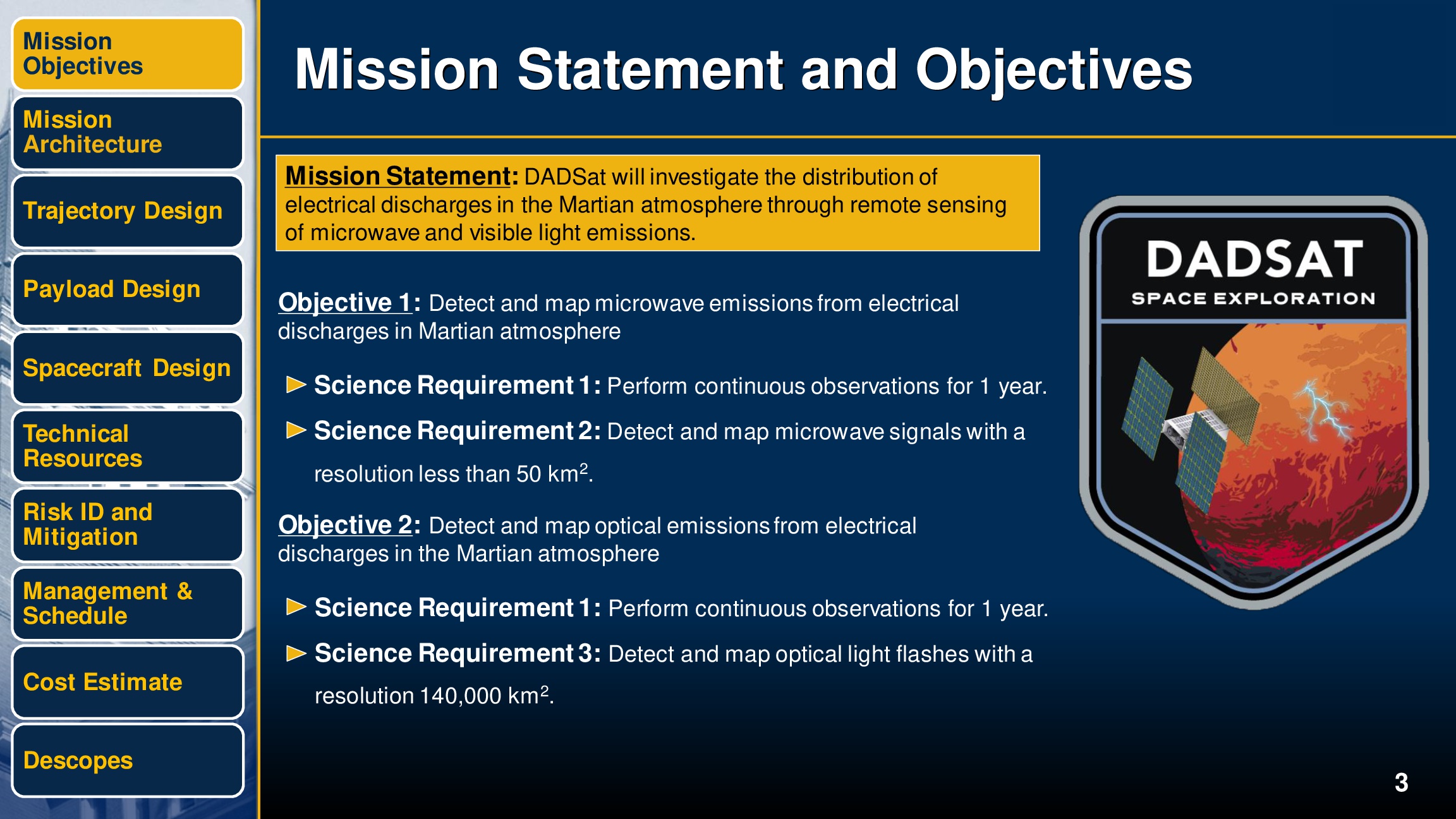
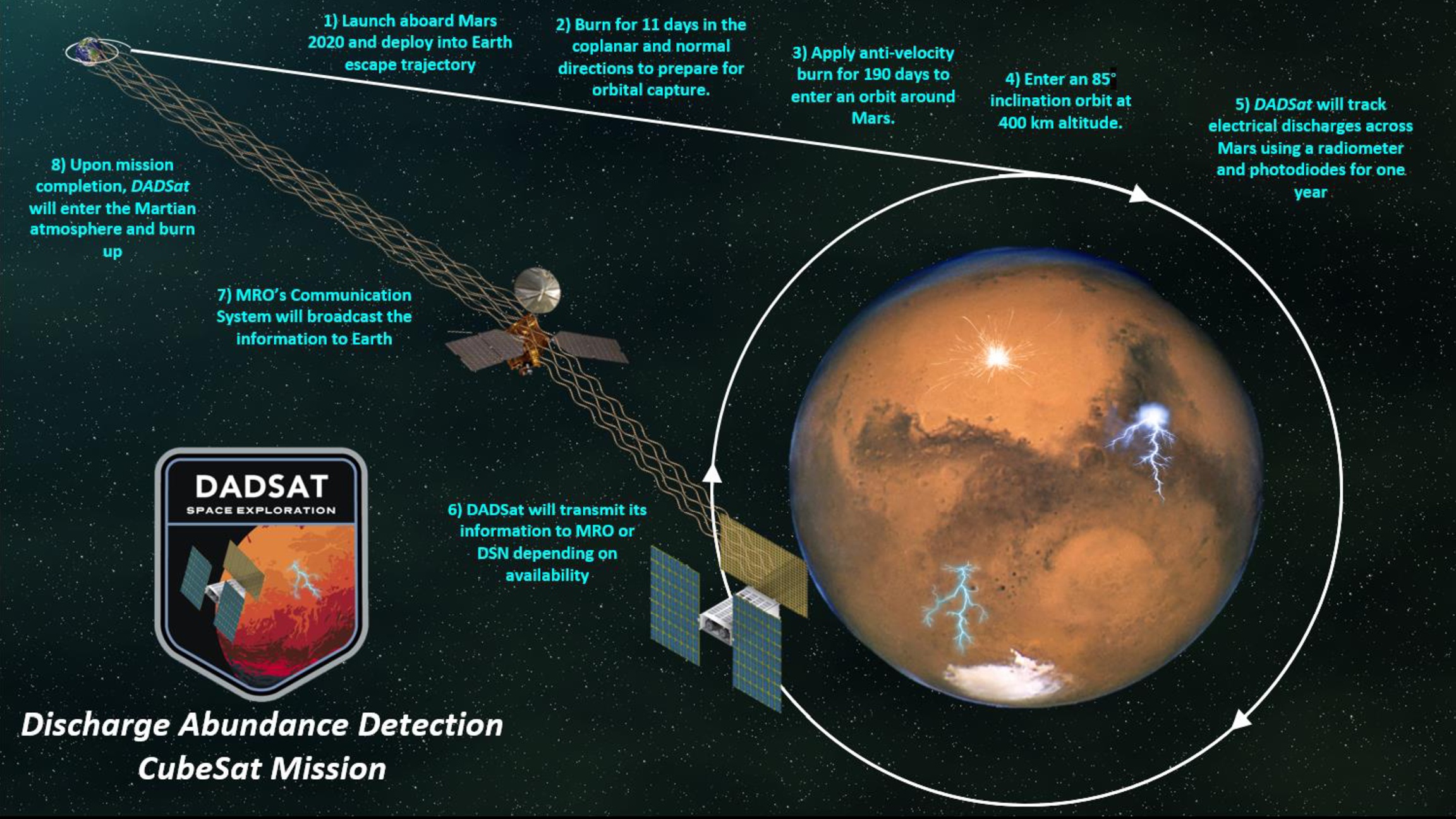
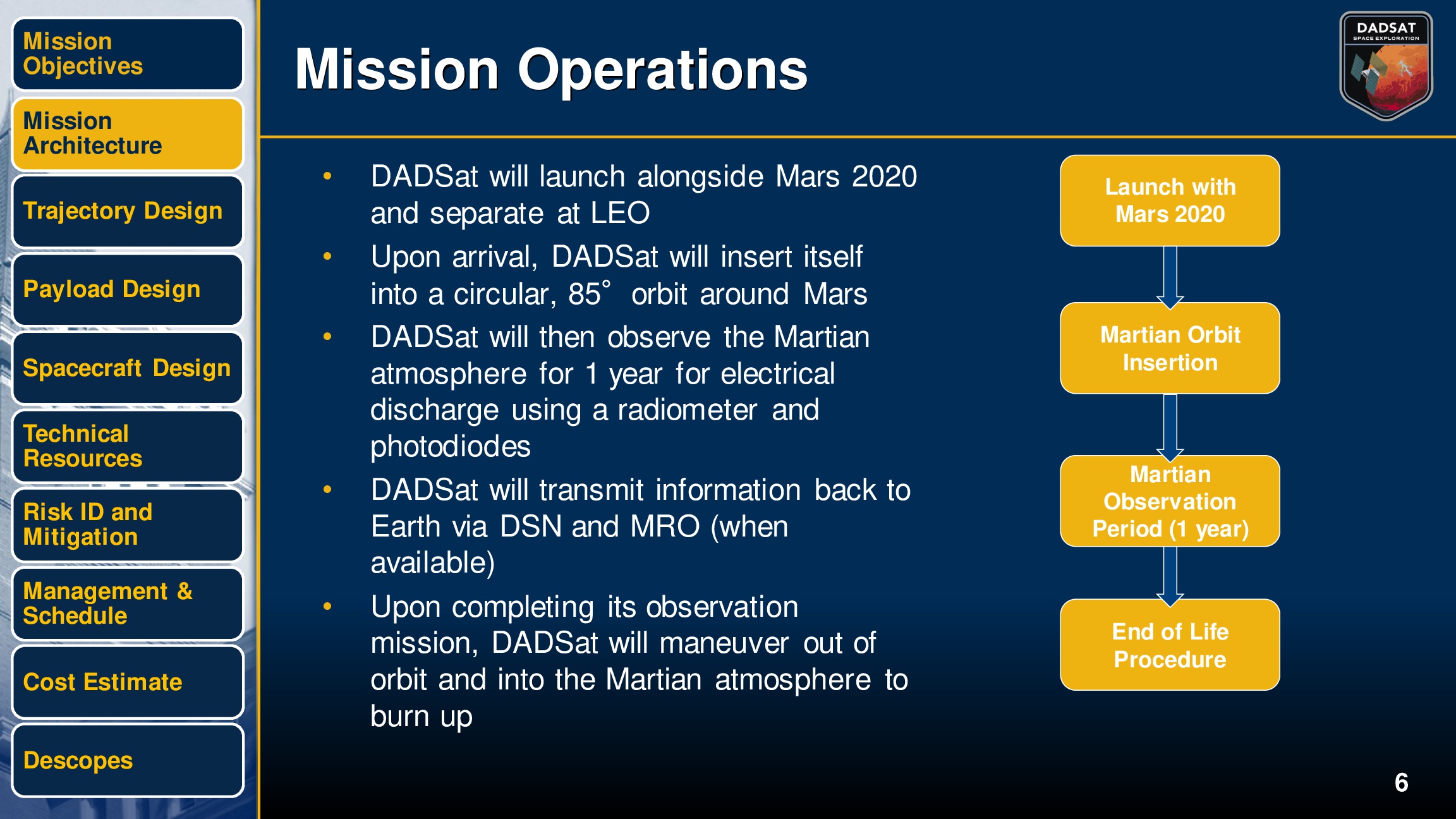
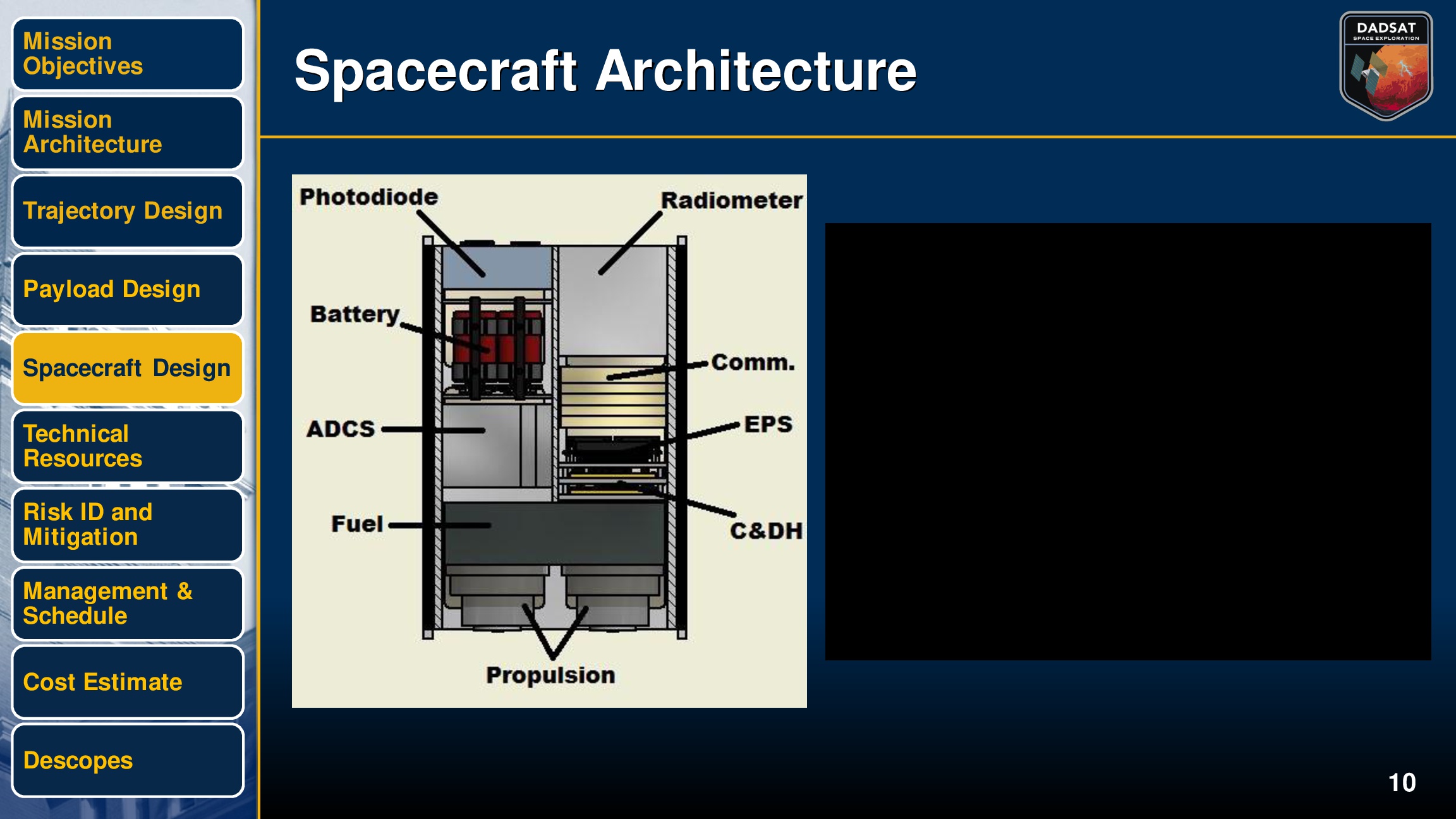
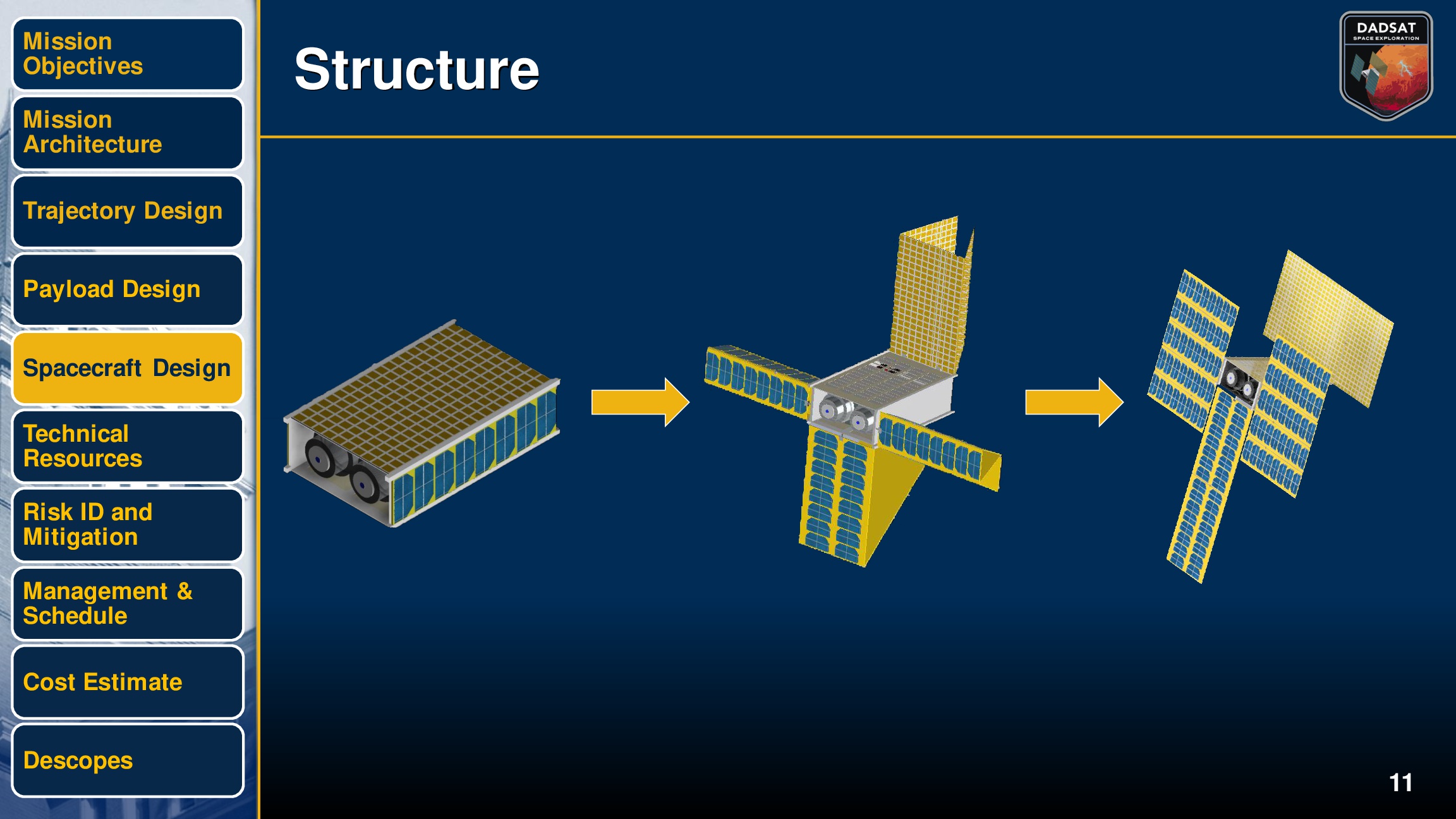
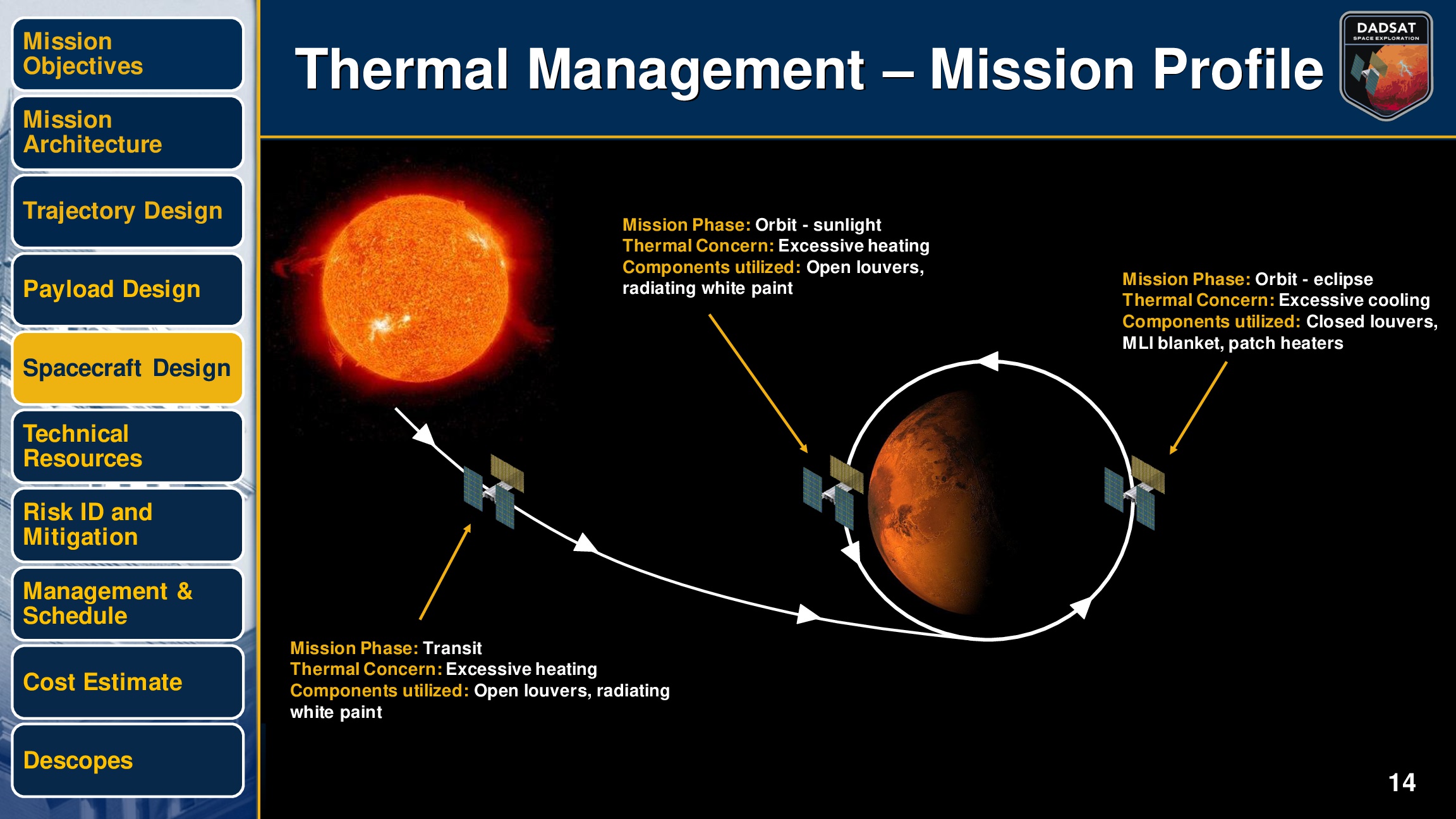
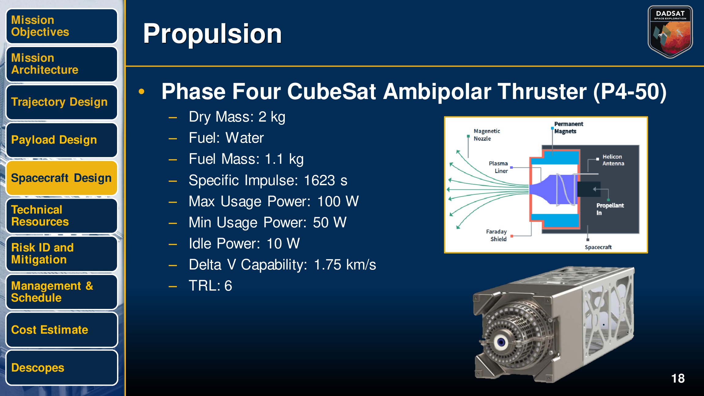
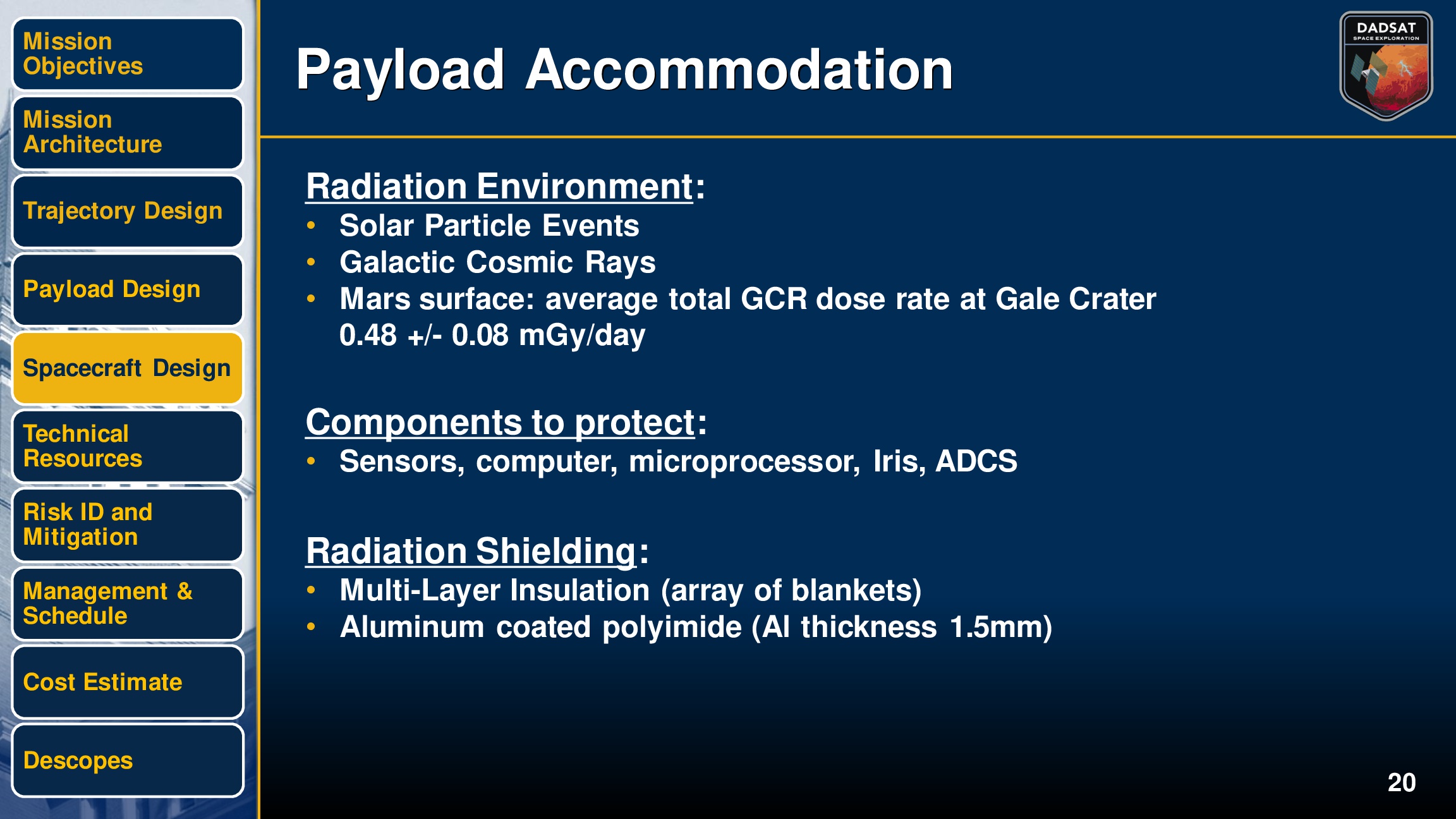
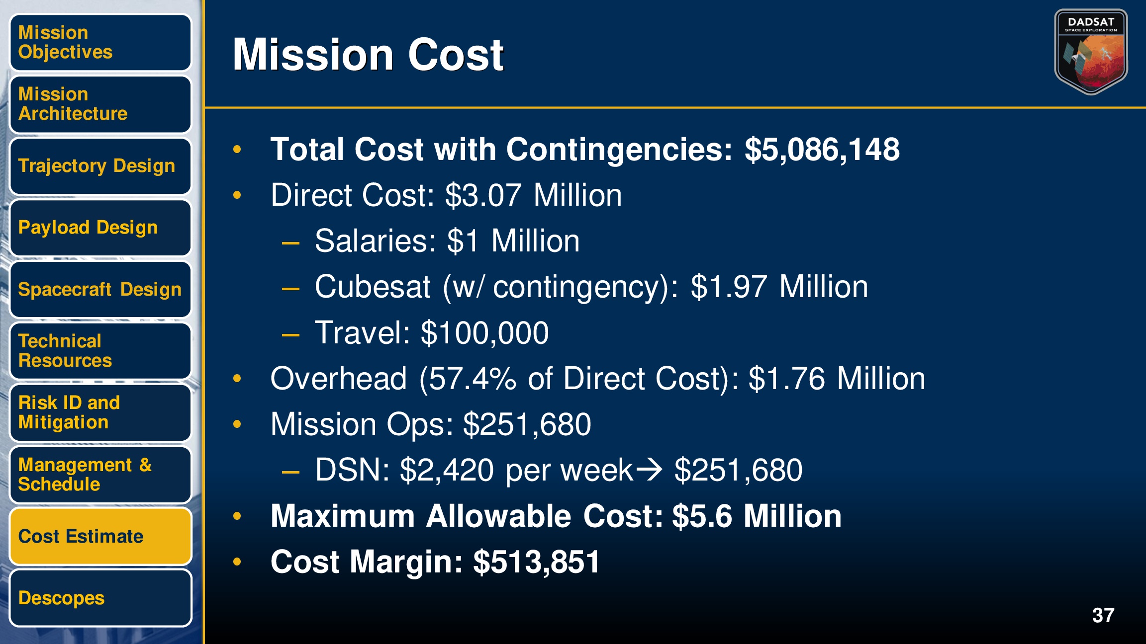
As part of our studies, I along with 9 of my peers carried out the design of a mission all the way out to a Preliminary Design Review (PDR). The mission was based on a focus on a response to the NASA Small Innovative Missions for Planetary Exploration (SIMPLEx) call. The limitations were that it had to be a nano/CubeSat mission with a maximum size of 6U, max cost of $6M, and lasting a total of 5 years. The mission had to be innovative and would launched along with the Mars 2020 mission. With these constraints in mind, my team opted for a satellite that would travel to Mars to detect and map microwave and optical emissions from electrical discharges in the Martian atmosphere.

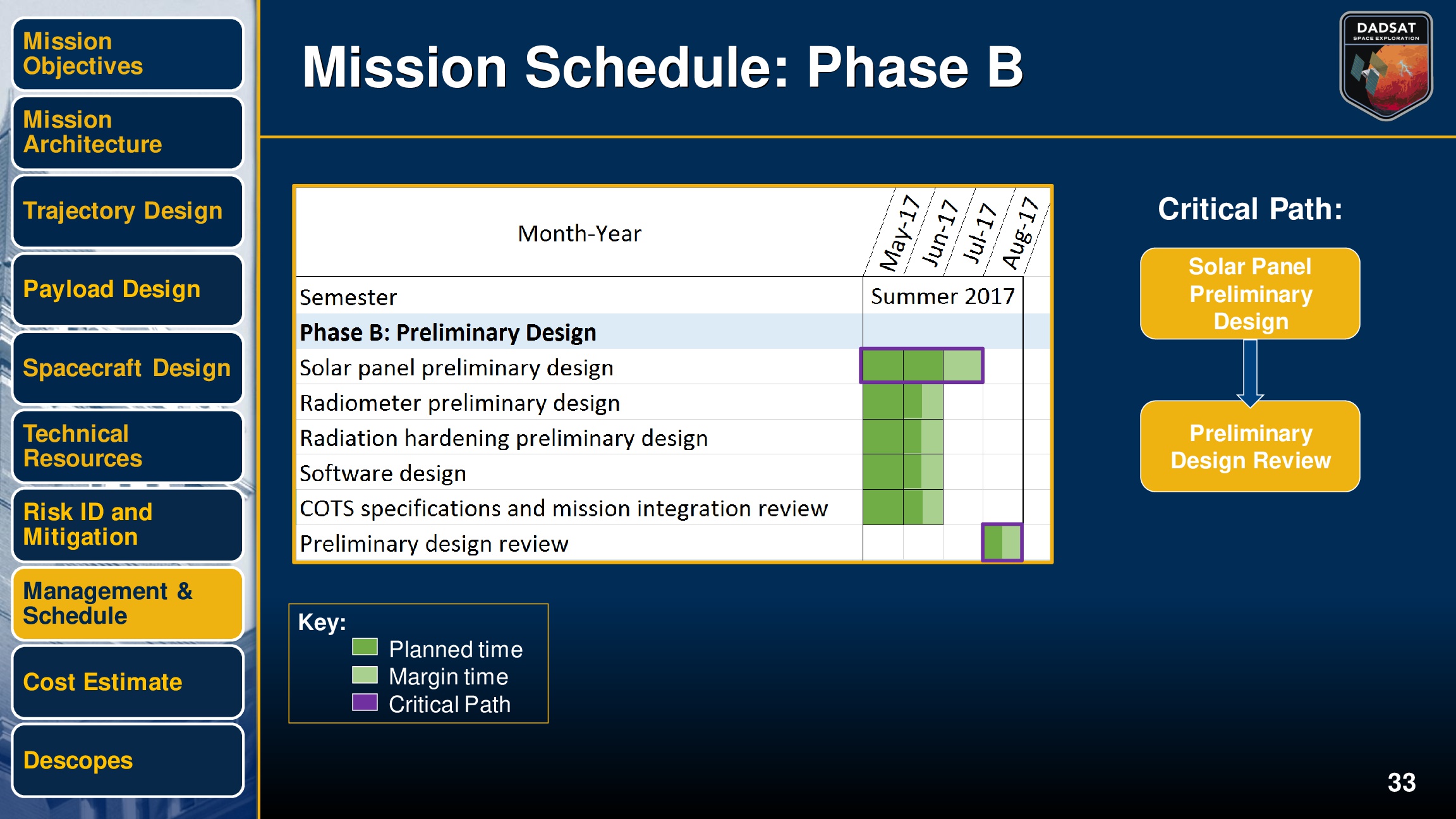
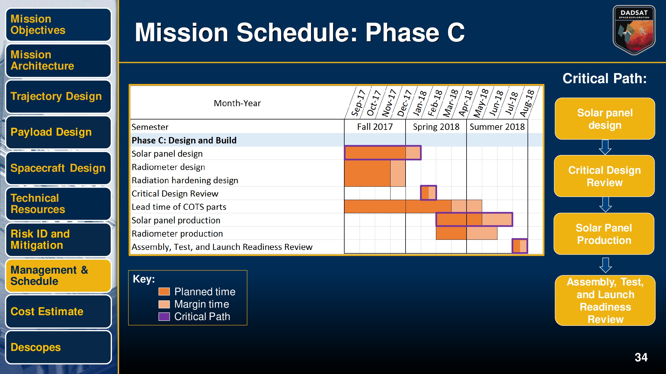
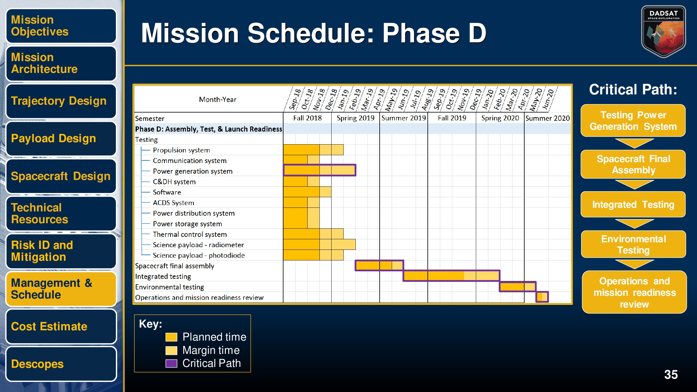
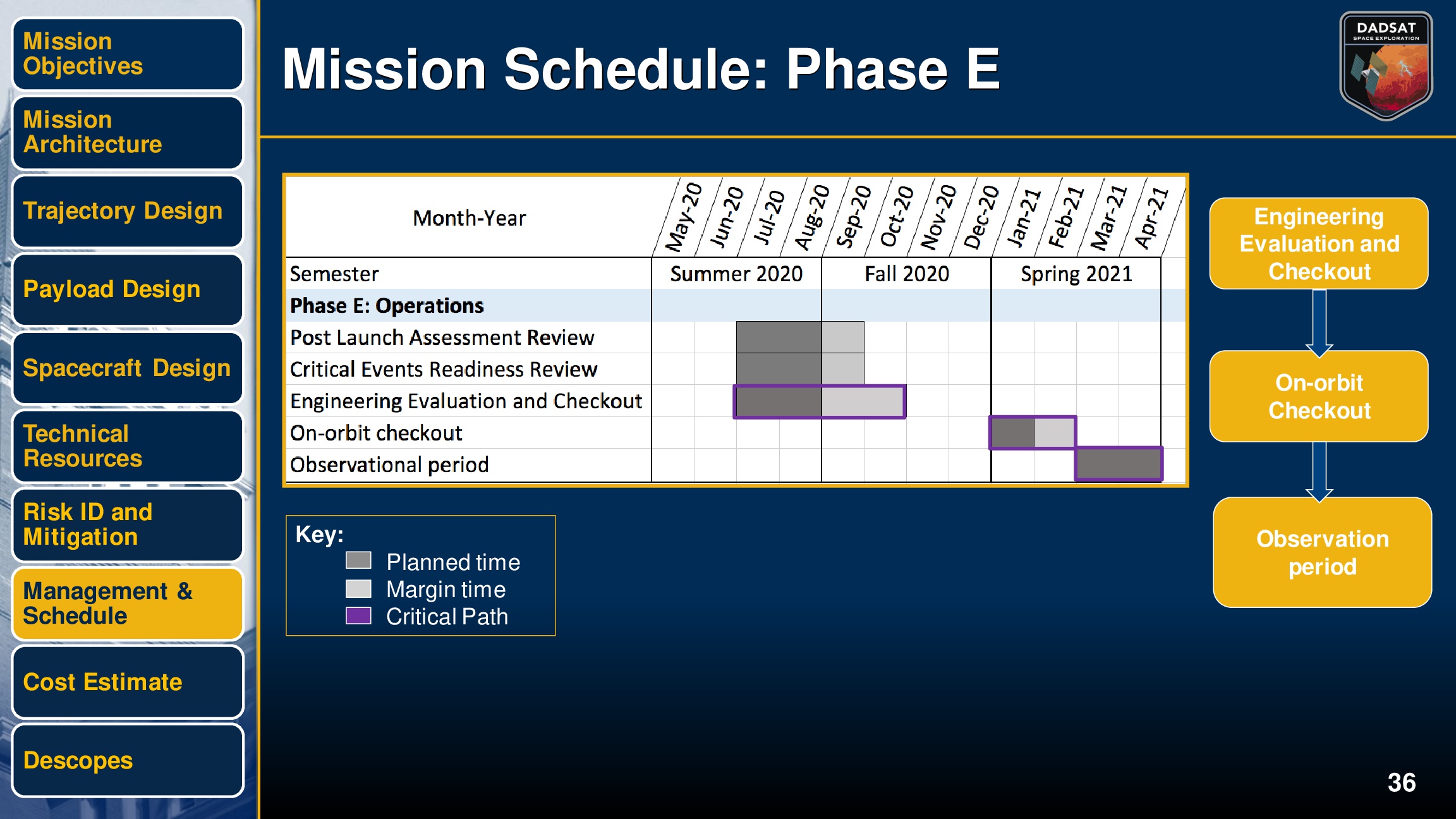
Before the final presentation, there were seven different reviews that were to be presented to our professor (who served as our Principal Investigator or PI). Each one focused on a different facet of the mission and provided us a general schedule on what milestones had to be completed in what order.

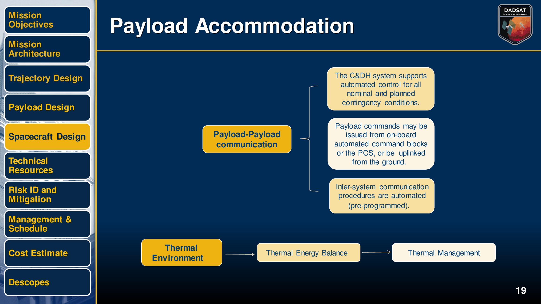
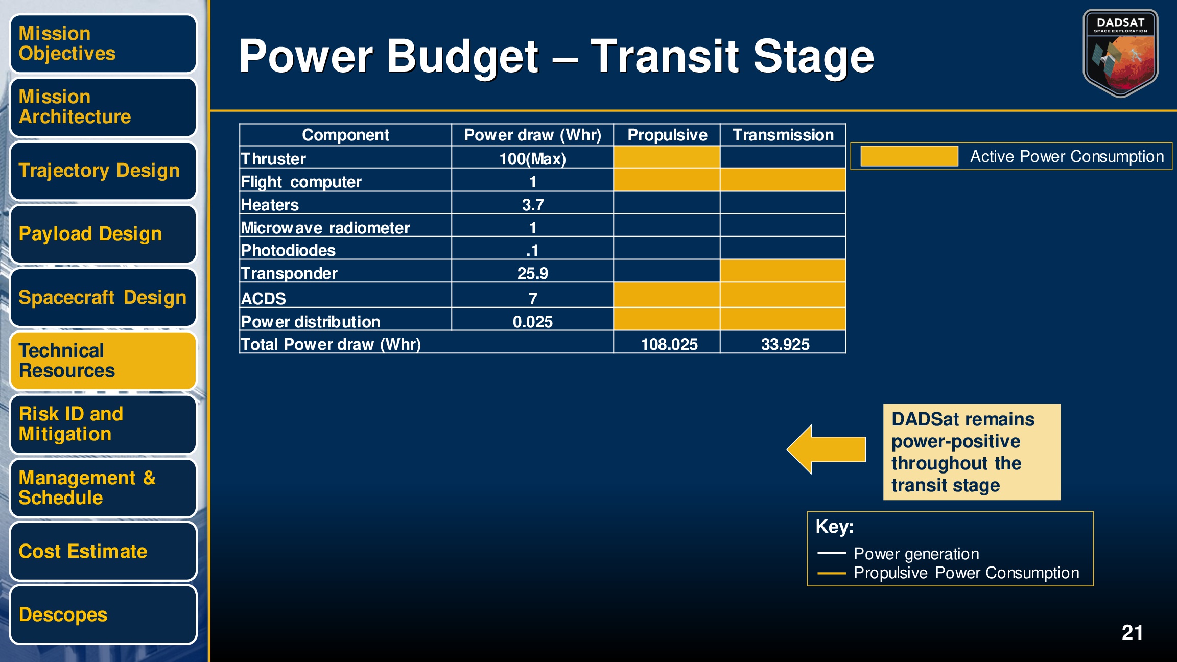
At the beginning of the project each team member was assigned a role. Some of those included Project manager and Systems Engineer. Although I was tasked as a systems engineer focusing on the orbit and command & data handling (CDH) capabilities of the spacecraft, all members of the team contributed to all aspects of the design.

The following is the summary of the mission that was presented to our professors, peers, and members of industry.

CFD Analysis of a 2D Airfoil

Although this was a relatively simple and straightforward project, it is what piqued my interest in aerodynamics, particularly CFD. It is now something I am exploring on my own time, and hope to be able to incorporate into my career.

Since we had not been exposed to CFD analysis before, we were walked through the majority of setting up the runs. The selection of which airfoil we were to analyze and the analysis itself was all individual. I chose the NACA 2412 airfoil since I had previously worked with that airfoil earlier in the semester.

The first step was generating the mesh for the analysis using Pointwise. The mesh was a Smooth O-Grid with a sharp trailing edge and 100 points over both the upper and lower surfaces. The spacing was 0.01 at the leading and trailing edges. The meshing parameters and the resultant mesh were as follows:

naca2412_pointdistribution.JPG
naca2412_mesh.JPG

The following were the physics models and boundary conditions that I chose to carry out the analysis using ANSYS Fluent.

PMandBC.PNG

The results from the analyses are presented below including the salient features for the flow.

naca2412_ppM.jpg
naca2412_ppP.jpg

Those results were then compared to the results of an analysis performed using XFOIL. The data for both analyses for the most part lines up, signifying agreeance between the different analyses. It was therefore concluded that the results are accurate.

naca2412_cp.jpg

Flight Dynamics of a Navion Aircraft

After a semester of Flight Dynamics we were assigned this project to tie in everything we had learned and to test our grasp of the subject. The project was split into three parts. The first part consisted of analyzing the flying qualities of Navion aircraft. This included the flight dynamic modes and mode shapes. These were computed from the linear models presented in this report. The following are the results.

Longitudinal
Eigenvalue Damping Ratio Frequency(rad/s) Mode
-2.4352+2.6461i 0.6772 3.5961 Short-Period
-2.4352-2.6461i 0.6772 3.5961 Short-Period
-0.2005+0.2593i 0.6118 0.3278 Phugoid
-0.2005-0.2593i 0.6118 0.3278 Phugoid
Lateral
Eigenvalue Damping Ratio Frequency(rad/s) Mode
-5.8461 N/A N/A Roll
-0.5077+2.3598i 0.2103 2.4138 Dutch Roll
-0.5077-2.3598i 0.2103 2.4138 Dutch Roll
-5.733e-4 N/A N/A Spiral

The second part consisted of modifying the dynamic models to account for a sensor pod attached to the aircraft. The shape of sensor pod was a 3 foot cube attached to the aircraft via an 8 inch cylinder with a 4 inch diameter. We assumed that the sensor pod had its own flying qualities and so therefore they could be determined independently and just added to the aircraft's. It was also shown that the sensor only affected the longitudinal modes. Those are presented below.

Sensor Longitudinal
Eigenvalue Damping Ratio Frequency(rad/s) Mode
-0.00399 N/A N/A N/A
-0.595 N/A N/A N/A
0.293+0.513i 0.497 0.591 Phugoid
0.293-0.513i 0.497 0.591 Phugoid

So the total modes were the following.

Total Longitudinal
Eigenvalue Damping Ratio Frequency(rad/s) Mode
-2.133+4.382i 0.4377 4.874 Short-Period
-2.133-4.382i 0.4377 4.874 Short-Period
-0.508+0.295i 0.865 0.588 Phugoid
-0.508-0.295i 0.865 0.588 Phugoid

Finally the third part consisted of performing a parametric trade study on the geometry of the pod to determine how the dynamic modes and mode shapes change as a function of the size of the sensor pod.  The results are presented below.

After the in-depth analysis of the Navion aircraft before and after the addition of the sensor pod, several observations and conclusions can be made. The only modes that were significantly affected were the Phugoid and rolling modes, which was predicted through theory. Overall the flying qualities of the Navion aircraft remained within acceptable parameters making the Navion an excellent aircraft.


*DISCLAIMER: This was a group project i.e. I did not do the analysis, evaluations, and write up by myself. It was a collaborative effort between myself and Alex Naber (B.S. Aerospace Engineering, Georgia Tech 2017).

Turbine Engine Cycle Design

The task was to derive a set of equations for a turbine engine that described the thermodynamic changes across each stage or component in the engine, and also engine performance parameters such as specific thrust and efficiency. Then it was necessary to develop a computer program that could model the engine cycle analysis for several different cases. In other words, a model that could model engines that included variations of combinations of the components analyzed.

After the set of equations was derived it was necessary to design four different cases of engines and find the maximum thrust of each of the engine cycles. The first a commercial airliner in ground roll and high altitude subsonic cruise, and a long range missile at low altitude subsonic cruise and high altitude supersonic cruise. Then it was necessary to pick or design a new engine cycle that satisfied both conditions required for each aircraft.

In order to develop the set of equations, the first step was to analyze each individual component of the engine, for an engine that contained every component. That way the results could be generalized to equations with less components, without loss of continuity. The following is the process used to derive the equations.

Then Mathematica was used to be able to perform quick analysis of different engines. With given inputs, a program was written that worked through each component determining thermodynamic changes utilizing the set of equations that was derived.

Once the equations were derived, an iterative technique was used to find the values of bleed, bypass, and fuel air ratios for the main burner and afterburners. The process to derive these equations and the resultant equations are presented below.

Once these were obtained, the maximum thrust was for the four specific cases was derived and are summarized in the table below. Overall this was a great project to learn about engine design and applications of thermodynamic concepts. It is something that I plan on exploring in the future, designing more complex (and sometimes theroetical) engines.